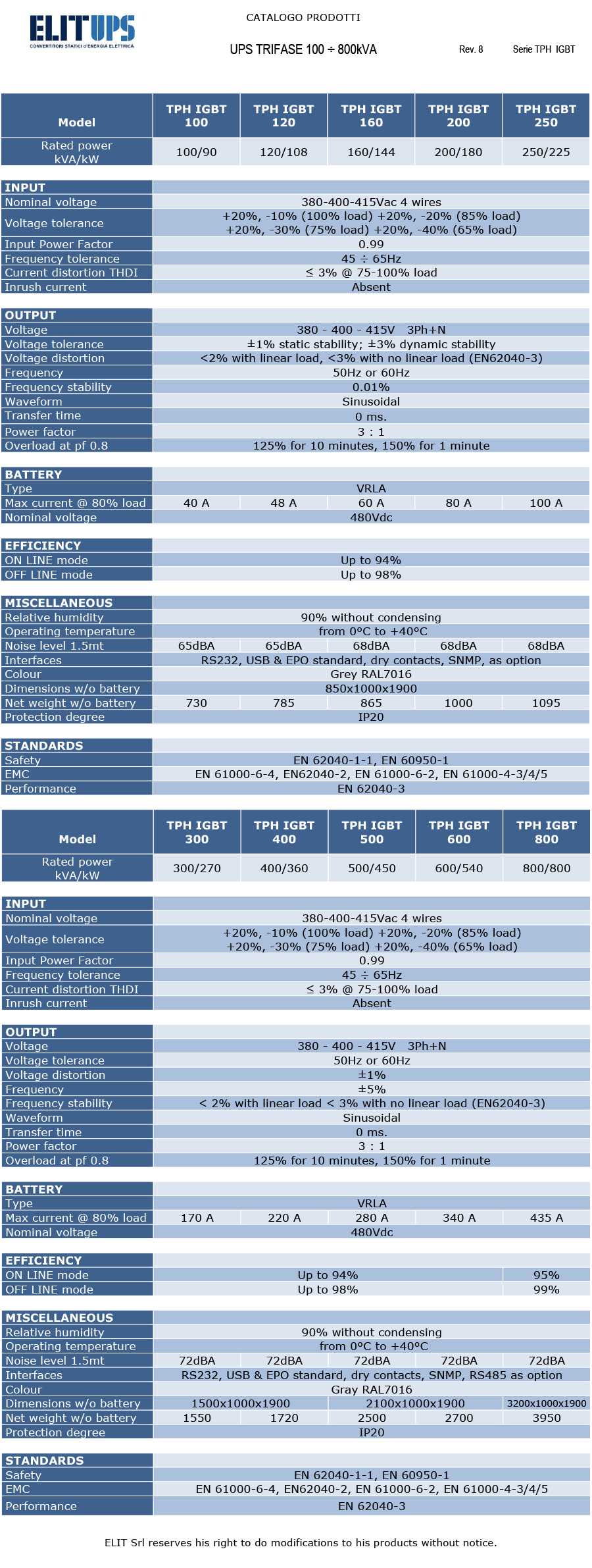
TPH IGBT series represents the latest generation of UPS in three-phase high-power transformer (VFI-SS-111) designed to protect a wide area of critical applications. For technology, performances (Eco Mode selectable from the panel), LCD display for alarms, measurements and historical events, 2 serial interface, RS232 and dry contacts, the series TPH IGBT is the perfect solution for powering all the sensitive electronics and security devices such as electro, data centers and telecommunications, industrial processes and systems of centralized power as required by EN 50171. All UPS TPH IGBT series can mount the main systems of communication interface such as dry contact interface, second RS232, RS485, USB, remote panel LCD, with SNMP software.
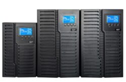
THREE PHASE UPS 100 – 800KVA, TPH IGBT SERIES
Description
- Input power factor 0.99 at full load
- Output power factor 0.9
- Input current distortion THiD ≤ 3%
- High efficiency up to 98% OFFLINE mode
- Parallelable up till 8 units (as option)
- Parallel configurations with central static switch
- IGBT inverter with transfomer
- Filtered, stabilized and regulated sine wave supply
- Wide input voltage window and input frequency window, the battery usage is minimized
- Zero transfer time
- Superior overload capability
- Battery monitoring and temperature dependent charging function as option
- LCD display for measurements, alarms and power history
- Back feed protection
- Device to avoid a complete battery discharge
- Cold start from battery as option
- Emergency line transformer as option
- ON LINE – OFF LINE working settable
- RS232 and standard dry contact, USB, RS485 and SNMP as option
- LCD remote panel as option
- Stabilizer function
- Static frequency converter function
- Emergency Power Off.
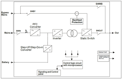
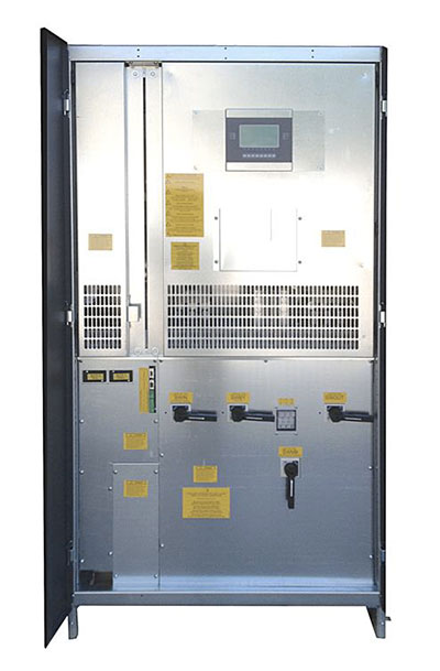
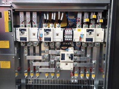
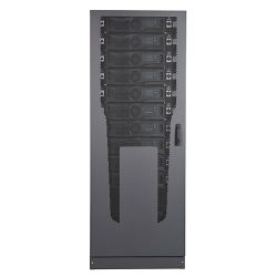
The backup series is composed by: Rectifier, Inverter with transformer, Static Switch, manual by-pass and Battery.
The Rectifier-Inverter line normally feeds the users, and the Battery is kept charged by the Rectifier.
If a black out occurs, the Battery supplies power energy to users always through the Inverter. When the blackout is over, the Rectifier provides for Battery charge.
If a short circuit or an overload occurs to the users, the Static By-pass switches the load over the emergency line. When the fault is over, the Inverter feeds users.
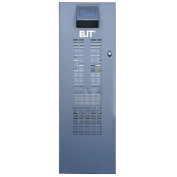
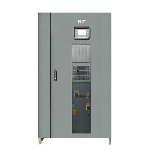
The user friendly control panel si composed by three parts:
- Power Management LCD Display (PMD);
- LED indicators;
- Keys.
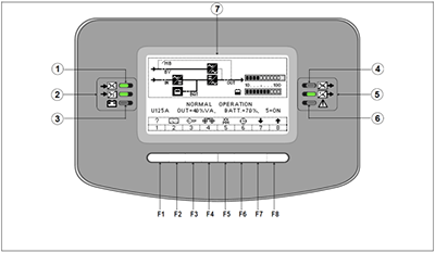
- Emergency line LED
- Mains LED
- Battery LED
- By-pass LED
- Output LED
- Alarm LED
- LCD display
- F1 keys
Power Management Display (PMD)
The LCD display simplifies the communication with the UPS and provides the necessary monitoring information about the UPS.
The menu driven LCD enables the access to the:
- Event log;
- Monitor the input and output U, I, f, P;
- Battery runtime;
- Start up and shutdown of UPS;
- ON LINE – OFF LINE modality settable;
- Diagnosis (Service Mode);
- Adjustments and testing.
LED indicators
The mimic diagram serves to indicate the general status of the UPS. The LED indicators show the power flow status and in the event of mains failure or load transfer from inverter to by-pass and vice-versa. The corresponding LED indicators will change colors from green (normal) to red (warning).
Keys
The keys allow the user to operate the UPS to perform settings and adjustments, to start up and shut down the UPS, to monitor on the LCD display the voltages, currents, frequencies and other values.
The TPH IGBT is provided with three standard interfaces:
- Serial RS232
- Service USB port
- Emergency Power OFF (EPO)
Serial RS232
The smart port is an intelligent RS232 serial port that allows the UPS to a computer. The connector is a standard D-Type, 9 pin, female.
The software optionally allows the computer to monitor the mains voltage and the UPS status continuously.
Serial RS485
The RS485 interface allows configuration of local networks at low cost and multipoint communications via ModBus / JBus.
Emergency Power Off
The Emergency Power Off facility must use a normally closed contact, which opens to operate the emergency stop sequence.
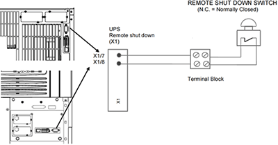
The emergency stop port is located at the front of the UPS TPH IGBT module. In order to allow removal, maintenance or testing of any remote emergency stop facility without disturbing the normal operation of the UPS, it is recommended that a terminal block, with linking facilities, be installed between the UPS and the stop button.
- Use a screened cable with 1 pair (section of wire 0.6mm2) and maximum length of 100m.
- Connect the cable as shown in figure.
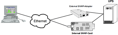
SNMP card for monitoring and integration in network management. The Simple Network Management Protocol (SNMP) is a worldwide-standardized communication-protocol. It is used to monitor any device in the network via simple control language.
Dry contact interface
Optional relay card to monitor the main status of the UPS.
The TPH KING UPS may be paralleled for power capacity or for redundancy up to 20 units to increase the power capacity or configuring a parallel redundant UPS system. The standard version is not provided with this feature which is optional and field upgradable.