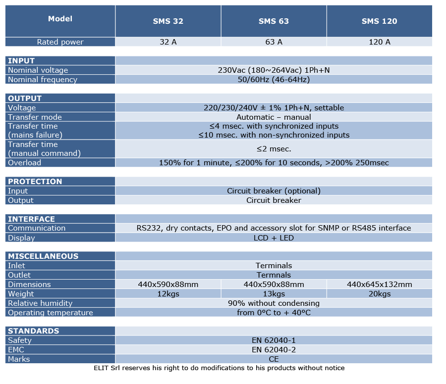
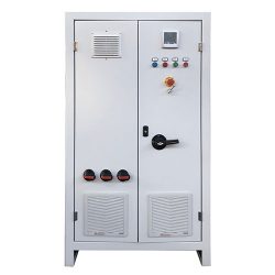
The SMS series devices are single-phase automatic transfer systems designed and built to guarantee the highest levels of performance.
POWER TRANSFER SYSTEM, SMS SERIES
Description
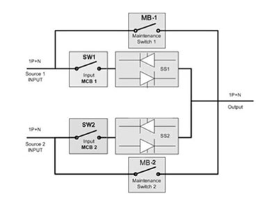
The single-phase SMS series, available in 32A, 63A and 120A rated power, is a simple and effective solution to manage the redundancy provided by two independent power sources, synchronous or asynchronous sources, allowing automatic or manual transfer of loads without interrupting the power supply to the load.
One of the two sources can be designated as a primary energy source, while the other becomes the alternative source. In the event of a failure, the transfer from one source to another is automatic and instantaneous. The SMS provides the possibility to set the values of the sources so that the transfer is done under certain voltage or frequency conditions set via software. The system constantly monitors the 2 power sources; whenever the line feeding the load exits the correct tolerance range (user-definable), the load is automatically transferred to the alternative (secondary) power source. The return to the preferred source is automatic when the voltage returns within the tolerance range. To provide a maximum level of protection for connected equipment, both power sources must be online UPS.
The SMS module can also be provided by a UPS and another type of source, or by two non-UPS sources that provide a sinusoidal output.
The use of the autumatic transfer system SMS series thus provides a secure protection against potential interference in the source that feeds the load or even in any power outages that may occur.
- Two separate synchronous or asynchronous independent sources
- Redundant power supply
- Transfer time ≤4 msec for synchronous source
- High reliability
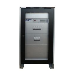
- Intuitive operation with LCD display
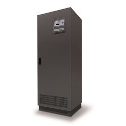
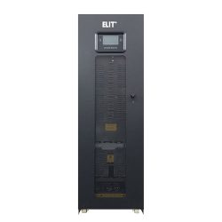
- 19″ rack configuration
- Hot-swap maintenance bypass included
- Available in 120Vac version
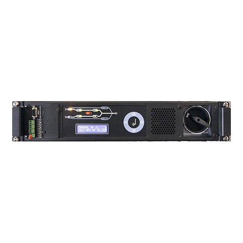
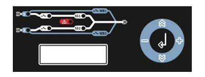
The front panel provides all the major parameters and the operating status of the SMS, which includes complete diagnostics and a simple user interface.
The input and output connections are located on the back of the SMS.
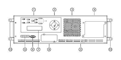
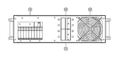
Elements and description:
- LEDs synoptic panel.
- Keyboard.
- Fan.
- Manual bypass.
- Dry contacts.
- RS232 interface.
- LCD display.
- Accessory slot for SNMP.
- Dry contacts.
- Source input switch 1.
- Source input switch 2.
- Fan.
- 19″ rack mounting.